Buck Converter Circuit Tutorial
In this tutorial we will learn how to build and how a DC to DC buck converter works. Types Circuit Design Modes of Operation Examples Losses and Applications.
Buck Boost Converters
The buck converter voltage step-down converter is a non-.
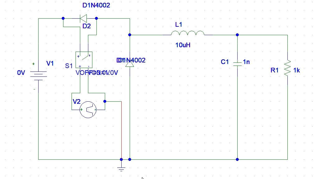
Buck converter circuit tutorial. Then well begin with the design philosophy for the input capacitors. All of the circuits in this tutorial can be simulated in LTspice. 1Step-up converter Boost Regulator2Step-Down converter Buck regulator 3Inverter Flyback In this tutorial we will describe the Switching Buck Regulator circuitWe already described the Buck Regulator Design in the previous tutorial.
If this is the case all equations in this document apply besides the power dissipation equation of the diode. DC-DC step-down Buck converter circuit. Buck Converter Design 4 Design Note DN 2013-01 V01 January 2013 1 Introduction A buck converter is the most basic SMPS topology.
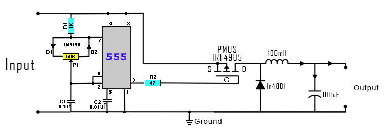
In order to efficiently reduce a high voltage to a lower voltage a buck dcdc converter. In this video you will find some examples on how to make your own buck converter circuit using the P-MOS IRF4905 but also the IRFZ44N N-MOS. Design of Buck Converter for 12V to 25V 1A.
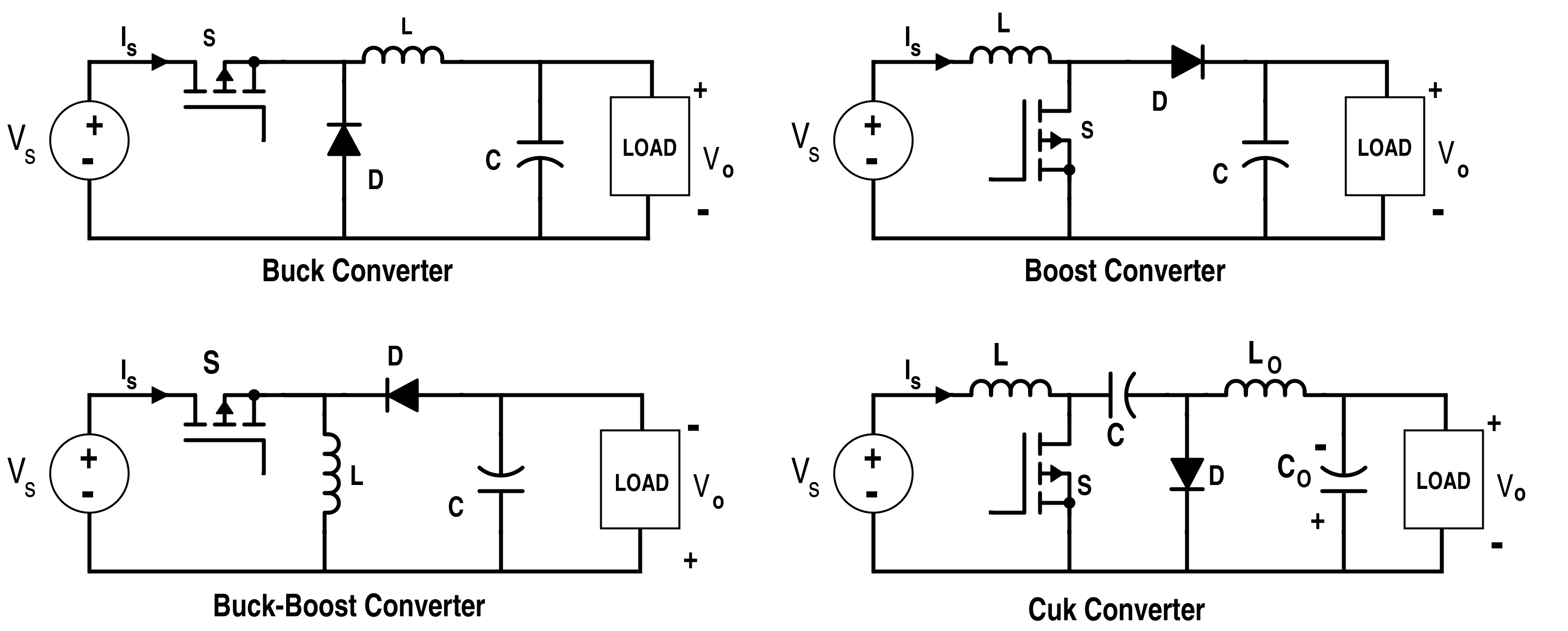
It is widely used throughout the industry to convert a higher input voltage into a lower output voltage. Buck Converter Tutorial If you use traditional linear output current power supply often then youll agree that its not so efficient. The basic components of the switching circuit can be rearranged to form a step-down buckconverter a step-up boost converter or an inverter flyback.
In the diagram of the current waveforms for the buck converter switching regulator it can be seen that the inductor current is the. The MOSFET output is prevented from increasing quickly as the inductor stores energy taken from the increasing output. The output voltage is equal to half the input voltage.
The step down buck converter circuit can be further explained by examining the current waveforms at different times during the overall cycle. Figure 3 below shows the corresponding circuit Figure 3. In the above video the author shows an efficient way to step down DC voltages by using buck converters.
These designs are shown in Figures 1 2 3 and 4. The buck converter is also known as a step-down converter since its output voltage must be less than the input voltage. Also you will le.
Buck Converter Power Stage 11 Necessary Parameters of the Power Stage. Buck Converter Design. Buck-Boost Converter DC-DC Regulator - summary or tutorial about the circuit and operation of a buck-boost converter a dc-dc converter able to provide voltages lower or higher than the input voltage.
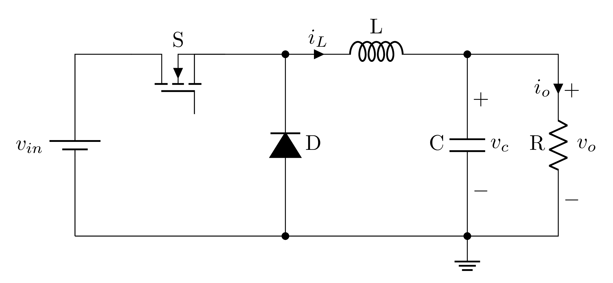
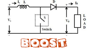
The circuit is very basic using just one diode an inductor and a capacitor. Here we will discuss different aspects of Buck converter and how to improve its efficiency. Integrated circuit IC.
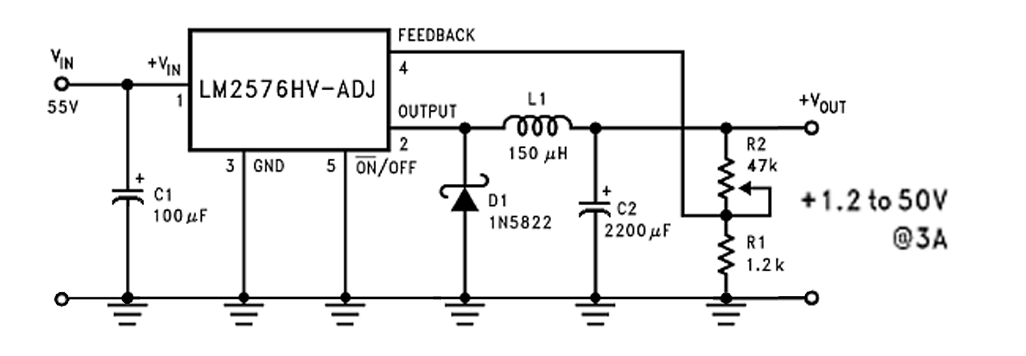
Before reading this section please read the introduction. The LM7809 voltage regulator is placed in the desired position on the circuit board. In this case a buck converter is a better output power option as it lowers input voltage effectively.
These designs are shown in Figures 1 2 3 and 4 respectively where Figures 3 and 4 are the same except for the transformer and the diode polarity. How to Build an Arduino-based BuckBoost Converter. There are three types of switching regulators available.
The above-presented circuit is a simple buck converter circuit in which the switch continuously switches between Vin and ground at a rapid rate with 50 duty cycle so circuit spends equal time in both levels. The Buck Regulator Power Supply Design Tutorial Part 2-1. If you are new to LTspice please have a look at my LTspice Tutorial.
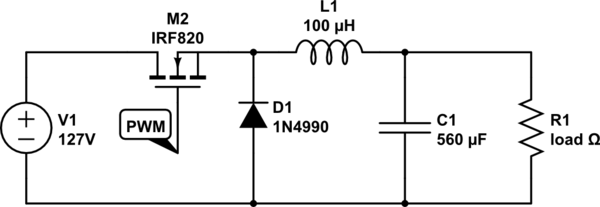
As discussed in the above section regarding how a buck converter works and as may be seen the following diagram the buck converter circuit includes a switching transistor and an associated Flywheel circuit which includes the diode D1 the inductor L1 and the capacitor C1. Some converters have the diode replaced by a second switch integrated into the converter synchronous converters. A switching regulator is a circuit that uses a power switch an inductor and a diode to transfer energy from input to output.
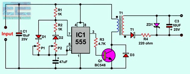
A Power MOSFET used as a controllable switch SW. The switch will be a MOSFET transistor and to create the PWM signal we will use a 555 timer in the PWM configuration boost adjustable controller or one Arduino NANO. This frequency is then fed to the switching device for the required buck converter actions.
The circuit for the DC-DC step-down Buck converter would have the LM7809 voltage regulator two capacitors with capacitance value of 033F and 01F. In Part 2-1 of our Power Supply Design Tutorial were going to start a deep-dive into the buck converter and select one very important part the output inductor. The basic components of the switching circuit can be rearranged to form a step-down buckconverter a step-up boost converter or an inverter flyback.
Buck converter circuit consists of four components. This stored energy is released back into the circuit when the MOSFET is rapidly switched off.
How To Draw A Dc Dc Buck Converter In Latex Using Circuitikz Tikzblog
Analysis Of Four Dc Dc Converters In Equilibrium Technical Articles
Dc To Dc Buck Converter Tutorial Maxim Integrated

Introduction To Buck Converter The Engineering Projects

Switching Buck Regulator Circuit Design Basics And Efficiency
Buck Converters
Buck Converter Simulation Using Pspice Tutorial 8

How To Generate Auxiliary Supplies From A Positive Buck Dc Dc Converter

Dc To Dc Buck Boost Converter Circuit Homemade
Dc Dc Converter Complete Guide Dc Dc Converter Circuit Examples
Dc To Dc Buck Converter Circuit Homemade Arduino
Buck Converter Simulation Using Pspice Tutorial 8

Buck Converter Design Tutorial Complete Equation Derivation And Design Sample

Buck Converter Design Tutorial Complete Equation Derivation And Design Sample

Buck Converter Design Template Mathcad Electronicsbeliever
Dc To Dc Buck Converter Circuit Homemade Arduino
Dc To Dc Buck Converter Circuit Homemade Arduino

Power Supply Design Notes Simulating A Buck Converter Power Electronics News

Power Supply Design Tutorial Part 1 2 Topologies And Fundamentals Continued Power Electronics News
Post a Comment for "Buck Converter Circuit Tutorial"